The processing coordinate system is the spatial reference your drone software uses to build orthomosaics, point clouds and elevation models. Esri’s Drone2Map documentation calls it the project coordinate system: the system of the 2D and 3D products after processing. Pick it once, name it in full, and use it for every capture of a site. Then each flight lines up with the last one, and measurements mean the same thing for you and your client.
This guide is for drone service providers, construction firms and property managers. It explains what the setting does, how to choose it, where it goes wrong and how to check it before you deliver. In DataDelivery, we organize every capture by property, site and date, so a consistent coordinate system is what makes comparing captures over time reliable.
TL;DR
- The processing coordinate system sets the reference for your final maps, models and measurements. Images may be geotagged in one system and delivered in another.
- Choose it from your ground control and from what the data must overlay, then use the same system for every capture of a site.
- A complete definition has four parts: horizontal datum and projection, vertical datum, geoid model and units.
- Most serious errors are silent: wrong vertical reference, swapped axis order, wrong UTM zone. Check against independent points before delivery.
- Document the system with its EPSG code (a numeric ID for a coordinate system) in every deliverable.
Table of Contents
- What a processing coordinate system is
- How to choose a processing coordinate system
- Transform correctly when systems differ
- Where a wrong coordinate system hurts
- Identify the coordinate system of your data
- Verify before you deliver
- Worked example
- Perspective
- Keep your coordinate systems organized with DataDelivery
- FAQ
- Sources
What a processing coordinate system is
A coordinate system describes how numbers map to places on Earth. A drone project usually involves several.
- Image coordinate system: the one used to geotag each photo. According to Esri’s RTK documentation, most RTK drones record WGS 1984 with ellipsoid height.
- Project (processing) coordinate system: the one your products are built in.
- Control coordinate system: the one your surveyed ground control points use. Outputs follow the imported control points’ system.
- Display system: what a map viewer draws on screen. It can differ from the data without changing it.
The same logic applies in GIS software. Esri’s ArcGIS Pro documentation says tools process data in the spatial reference of the output dataset, and inputs in other projections are brought into a common reference first. Processing and output share one system, so choosing the output system is choosing the processing system.
The four parts of a complete definition
- Horizontal datum and projection: for example NAD83(2011) with a State Plane zone or UTM zone.
- Vertical datum: for example NAVD88 (orthometric height, measured from a geoid) or WGS84 ellipsoid height.
- Geoid model: the surface that converts between the two, such as GEOID18 for the contiguous US.
- Units: meters, international feet or US survey feet.
Leave any of the four unstated and someone downstream will guess.
How to choose a processing coordinate system
Start from your control and your overlay data
The output system is dictated by your control, not by preference. If your control points and imagery disagree on datum, Bathyl’s practical guide says you have a transformation to do rather than a setting to flip. DJI Terra’s manual makes the same point: if you mark GCPs, the output system must match the GCP system or the output may not match the GCP coordinates.
Ask three questions:
- What system is the surveyor’s control in?
- What system do the engineer’s CAD files, parcel data or GIS layers use?
- What does the contract require?
The answers usually agree. When they do not, resolve it before the flight, not after processing.
Follow a public standard when one applies
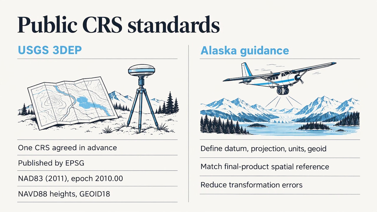
Federal and state specifications show what a well-defined choice looks like. The USGS 3DEP Lidar Base Specification requires data to be processed and delivered in a single CRS agreed in advance and published by EPSG. For the contiguous US it specifies NAD83 (2011 realization, epoch 2010.00), NAVD88 heights and the GEOID18 model.
Alaska’s aerial imagery guidance asks contracts to define datums, projections, units and geoid explicitly. It says imagery should be processed in the same spatial reference as the final products, to reduce transformation errors. That is a good habit for any private project too.
Know what software defaults do
Defaults are a starting point, not a decision.
- Drone2Map’s default is WGS84 horizontal and EGM96 vertical. With no control points and geographic image coordinates, it produces products in the local WGS84 UTM zone.
- DJI Terra sets a default from the photos’ position data: a known system when photos carry GPS, an arbitrary one when they do not. It also lets you search by name or EPSG code and import a PRJ file (a small file that describes a coordinate system).
A default WGS84 UTM output is fine for a quick visual map. It is rarely right for deliverables that must match survey or design files.
Keep large sites in one system
Pick one system per site and keep it for every capture. If a very large area would suffer unacceptable distortion in one system, the USGS specification says to split it into subareas, each delivered as a separate subproject with its own CRS and matching boundaries. Most construction sites and properties are far smaller than that.
Transform correctly when systems differ
Sometimes imagery is geotagged in WGS84 and control is in NAD83 with NAVD88 heights. Then you need a datum transformation: a mathematical conversion between two reference frames.
Per Esri’s transformation guidance:
- Define the transformation in project options before running the adjustment.
- Consider horizontal and vertical systems together. Converting to a NAVD88 vertical output also requires the right horizontal transformation, because NAD and WGS reference the Earth differently.
- An optimal transformation is suggested by default, and you can choose among geoids for WGS84-to-NAVD88 work.
- An incorrect pairing causes horizontal or vertical offsets.
Esri also recommends collecting control points in a projected system within the same geographic system as the drone imagery, which avoids transformations between geographic datums altogether.
Where a wrong coordinate system hurts
Vertical errors hide behind good-looking maps
The most common failure is vertical. Raw GNSS gives ellipsoidal heights, while engineers expect orthometric heights tied to a geoid. Bathyl describes GeoTIFFs that look right horizontally but sit 30 to 50 m off vertically. The error surfaces only when the DEM meets a total-station survey or a national lidar tile. The relationship is H = h − N, where N, the geoid undulation, varies by location and tilts slowly across a large site.
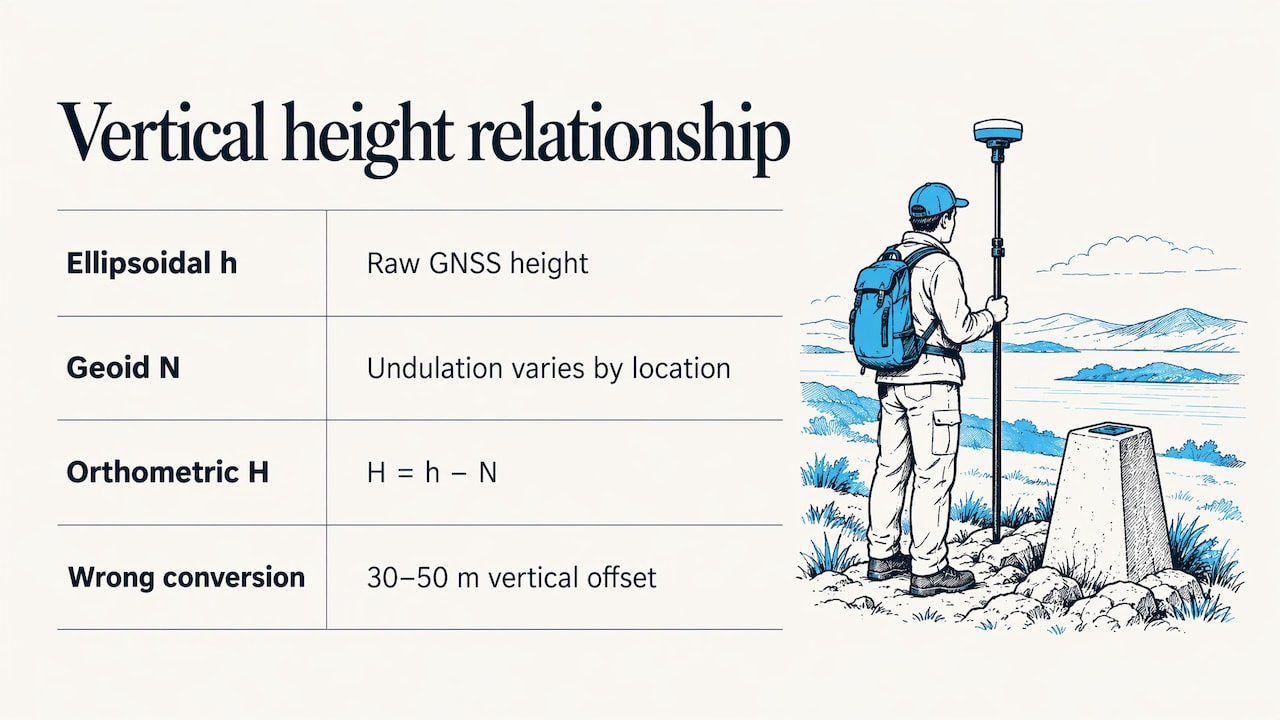
For earthwork, stockpile volumes and grading checks, that is not a rounding issue.
Distance and area depend on the system
Esri’s geoprocessing documentation shows features in Web Mercator (EPSG:3857) reporting 9,600 meters where a more accurate calculation gave 6,763 meters. Web Mercator is built for web display. Measure in a projected system suited to your site.
Units drift too
Meters and US survey feet differ by about 2 parts per million, and the gap accumulates in State Plane work, according to Bathyl. Always state which foot you mean.
Silent software traps
If you script conversions with Python, DronePhotogrammetry.org notes two quiet failures. EPSG:4326 declares latitude-longitude order while many files store longitude-latitude, so skipping always_xy=True can swap inputs and create an offset of 500 m or more. And a missing grid-shift file can make PROJ fall back to a coarse approximation without an error.
Identify the coordinate system of your data
Before processing or delivering, find out what each input uses.
- Look at the file metadata: GeoTIFFs and LAS/LAZ files often carry an EPSG code or WKT (a text definition of a coordinate system).
- Check the flight and control records, including the surveyor’s report.
- If the file has no CRS at all, use acquisition metadata and assign it deliberately. Python LiDAR’s CRS mismatch guide walks through this order of inspection for point clouds.
- Record the result with its EPSG code.
You can open a GeoTIFF or a LAS/LAZ file in our free GeoTIFF viewer or LAS and LAZ viewer to see how a file displays and sits on a map.
Verify before you deliver
A short, repeatable checklist keeps errors from reaching the client.
- Confirm the definition. Horizontal system with EPSG code, vertical datum, geoid model and units, all written down. Bathyl notes that “WGS84” alone is not a complete vertical statement.
- Check the bounding box. Coordinates should fall where the site actually is. Not-a-number or infinite values often mean the wrong UTM zone or hemisphere.
- Compare independent check points. Esri’s RTK/PPK guidance says check points remain essential even with RTK or PPK drones, because otherwise you cannot validate accuracy. Alaska’s guidance adds that check points must be independent of control used in the adjustment.
- Report the error. Published studies, such as this peer-reviewed orthophoto accuracy study, compare orthophoto coordinates of check points with field-measured values and report RMSE (root mean square error, a standard summary of positional error).
- Match the next capture. Overlay it on the previous one. A consistent shift across the whole site points to a system mismatch, not site change.
When specifying what a deliverable must state, a structured reporting template approach from the inspection field shows how fixed fields keep documentation consistent from job to job.
Worked example
A contractor wants monthly progress captures of a grading project, delivered against design files in NAD83(2011) State Plane, NAVD88 heights, US survey feet.
- The surveyor’s control uses that system, so it becomes the project system.
- The drone geotags in WGS84, so a transformation is defined before adjustment, with the matching geoid.
- After processing, the team compares five independent check points to field-measured values and records the RMSE.
- The metadata sheet lists the EPSG codes, geoid and foot definition.
- Every later month reuses the identical definition. Month-to-month surface differences now reflect earthwork, not a reference shift.
Perspective
Coordinate systems cause trouble when they live in one person’s head. We built DataDelivery around the idea that a site is a long-running record, organized by property, site and date, and that record only works if every capture shares one reference.
Our advice to drone service providers: decide the system with your client at the start, write it into the job, and keep it fixed for recurring captures. When captures share a system, map-based and timeline comparison show real change, annotations land where they belong, and reports are credible.
For construction teams and property managers, the payoff is simple. You open a site, step through dates, and trust that what moved on screen moved on the ground. That is the clarity we want every client to get from their aerial data.
the author
Keep your coordinate systems organized with DataDelivery
DataDelivery gives you one place to process, view and deliver orthomosaics, point clouds and 3D models, organized by property, site and date. You compare captures over time in map view, add annotations, measure stockpiles and contours, and share branded client portals without per-seat fees or required client accounts. Plans start with a FREE tier at $0 per month, and paid plans begin at $12.99 per month for Starter or $129 per year. See all tiers on the DataDelivery pricing page.

If you would rather not fly the site yourself, our turnkey aerial capture service is available through the National Drone Services site. To see how deliverables look to clients, read our guide to sharing orthomosaics with clients.
FAQ
What is the best processing coordinate system for drone mapping?
The one that matches your ground control and the files your deliverable must overlay. For many US construction projects that means NAD83(2011) with a State Plane or UTM projection and NAVD88 heights with the GEOID18 model. Agree it before the flight.
How do I find the EPSG code of my data?
Check the file metadata first, since GeoTIFF and LAS files often store an EPSG code or WKT definition. Then check the surveyor’s control report and flight records. Record the code in your deliverable notes.
Why does my map look right but my elevations are wrong?
Horizontal and vertical references fail independently. Heights left in WGS84 ellipsoid form can sit tens of meters from orthometric heights, so a map draws correctly while the surface is vertically off. Define the vertical datum and geoid explicitly.
Do I need ground control points if my drone has RTK?
RTK or PPK drones can produce high-accuracy products without GCPs. Check points are still essential, because without them you cannot validate accuracy, according to Esri’s documentation.
Sources
- Specify a datum transformation, ArcGIS Drone2Map
- Real-time and post-processed kinematic processing, ArcGIS Drone2Map
- Spatial reference and geoprocessing, ArcGIS Pro
- Aerial Imagery Collection Guidance, Alaska GeoPortal
- Lidar Base Specification 2021 revision A
- Processing options, ArcGIS Drone2Map
- DJI Terra User Manual, coordinate system
- CRS for Drone Mapping Outputs: A Practical Guide, Bathyl
- Coordinate system considerations for geoprocessing, ArcMap
- Converting WGS84 to Local Grid with Python, DronePhotogrammetry.org
- Fixing CRS Mismatches in Point Clouds, Python LiDAR
- Generating a High-Precision True Digital Orthophoto Map, MDPI